The Aluminum Association Tolerances For Aluminum Extrusions

Table 11.2 Cross-Sectional Dimension Tolerances - Profiles

Table 11.2 Cross-Sectional Dimension Tolerances.pdf

Footnotes for Tables 11.2 through 11.4

(1) These Standard and Precision Tolerances are applicable to the average profile. The extrusion conditions required to produce the wide variety of alloy-temper and profile combinations require close review between customer and producer to determine critical characteristics and tolerance capability, aggressive profile characteristics may require wider than standard tolerance and closer than precision tolerance may be feasible for other characteristics.

(2) The tolerance applicable to a dimension composed of two or more component dimensions is the sum of the tolerances of the component dimensions if all of the component dimensions are indicated.

(3) When a dimension tolerance is specified other than as an equal bilateral tolerance, the value of the standard tolerance is that which applies to the mean of the maximum and minimum dimensions permissible under the tolerance for the dimension under consideration.

(4) Where dimensions specified are outside and inside, rather than wall thickness itself, the allowable deviation (eccentricity) given in Column 3 applies to mean wall thickness. (Mean Wall thickness is the average of two wall thickness measurements taken at opposite sides of the void.)

(5) In the case of Class 1 Hollow Profiles the standard wall thickness tolerance for
extruded round tube is applicable. (A Class 1 Hollow Profile is one whose void is round
and one inch or more in diameter and whose weight is equally distributed on opposite
sides of two or more equally spaced axes.)

Table 11.5 Length(1) - Wire, Rod, Bar, and Profiles

Table 11.6 Straightness (1) - Rod, Bar and Profiles

Footnotes for Tables 11.5 through 11.8

(1) These Standard Tolerances are applicable to the average profile; wider tolerances may be required for some profiles, and closer tolerances may be possible for others.

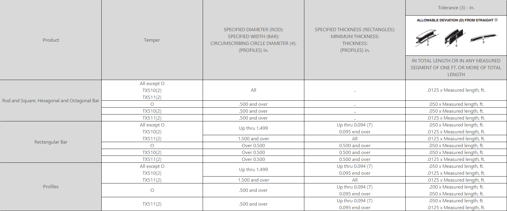
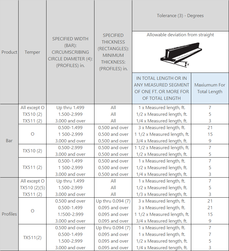
(2) TX510 and TX511 are general designations for the following stress relieved tempers: T3510, T4510, T61510, T6510, T8510, T73510, T76510 and T3511, T4511, T61511, T6511, T8511, T73511, T76511, respectively.

(3) When weight of piece on the flat surface minimizes deviation.

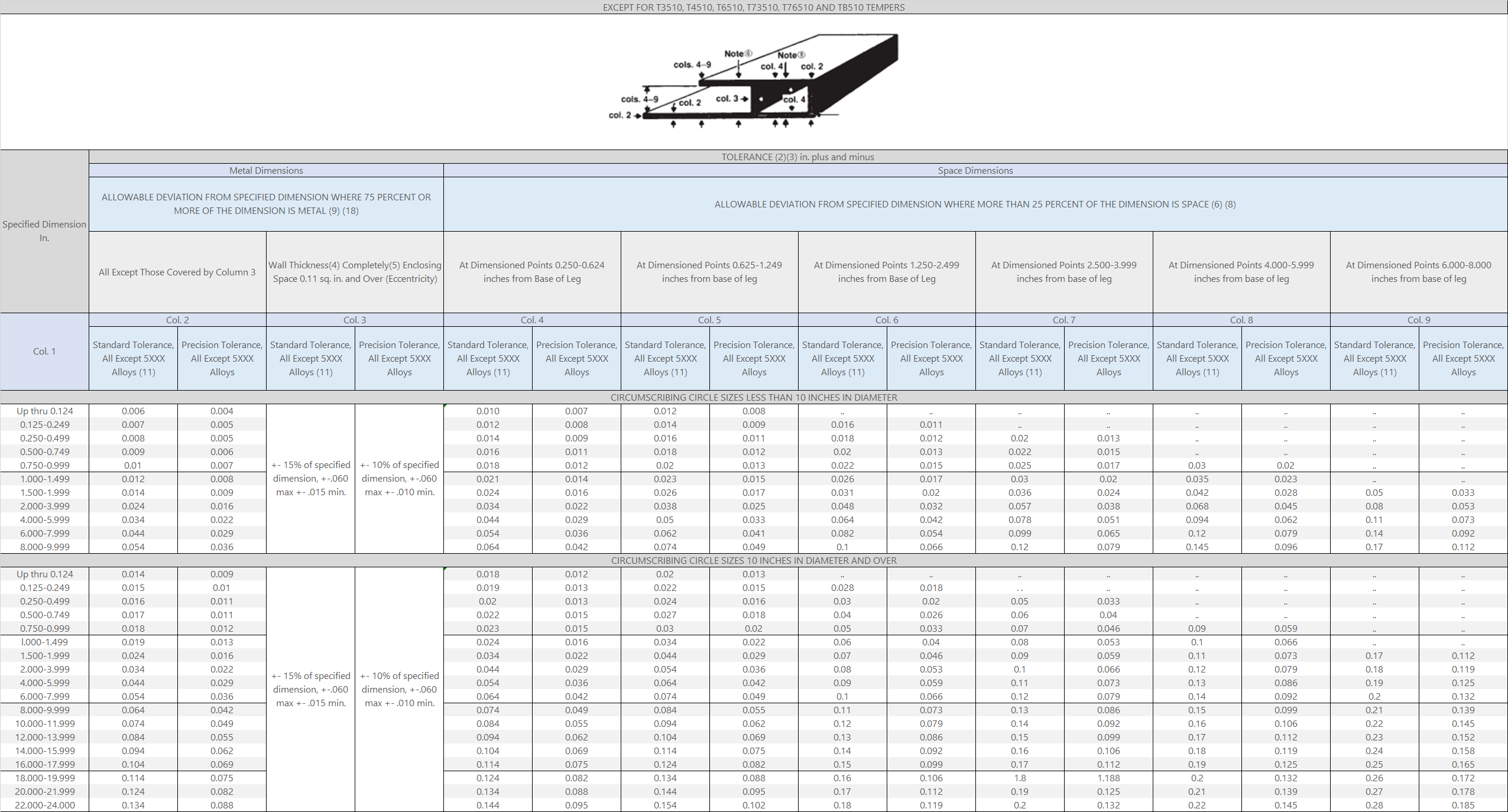
(4) The circumscribing circle diameter is the diameter of the smallest circle that will completely enclose the cross section of the extruded product.

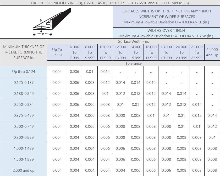
(5) Tolerances for T3510, T4510, T6510, T73510, T76510, and T8510 tempers shall be as agreed upon between purchaser and vendor at the time the contract or order is entered.

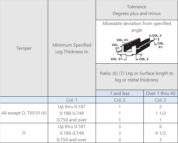
(6) Twist is normally measured by placing the extruded section on a flat surface and at any point along its length measuring the maximum distance between the bottom surface of the extruded section and the flat surface. From this measurement, the actual deviation from straightness of the
extruded section at that point is subtracted. The remainder is the twist. To convert the standard twist tolerance (degrees) to an equivalent linear value, the sine of the standard tolerance is multiplied by the width of the surface of the section that is on the flat surface. The following values are used to convert angular tolerances to linear deviation:

Maximum Allowable

(7) Applies only if the thickness along at least 1/3 of the total perimeter is 0.094 or less. Otherwise use the tolerance shown for 0.095 and over.


(8) Tolerance for “O” temper material is four times the standard tolerances shown.


(9) Straightness must be met in all orientations, including orientations which are not self-supporting.

TABLE 11.7 Twist (1) (6) - Bar and Profiles

TABLE 11.8 Flatness (Flat Surfaces)(1) - Bar, Solid Profiles and Semihollow Profiles

Table 11.9 Flatness (Flat Surfaces) (1) - Hollow Profiles

Table 11.10 Surface Roughness (1) (8) - Extruded Wire, Rod, Bar and Profiles

Table 11.11 Contour (Curved Surfaces) (1) (3) - Extruded Profiles

Allowable deviation from square: 1 degree

Table 11.12 Squareness of Cut Ends (1) - Extruded Rod, Bar and Profiles

Allowable deviation from square: 1 degree

Table 11.13 Corner and Fillet Radii (1) - Extruded Bar and Profiles

Table 11.14 Angularity (1)(5) - Extruded Bar and Profiles